Truss Deck Crack Detection Plan
Release Date:
2025-07-07
Information Summary:
1. Transportation and Storage:
1) Truss‑type composite panels shall be transported to the site using dedicated protective measures. The storage area for these panels must be level and paved, with shims placed beneath each panel.
2. Visual inspection of truss composite panels and the number of samples to be inspected:
1) Inspect the geometric dimensions of the truss composite slab; if there are no chipped corners or cracks, and all parameters meet the criteria specified in the appearance quality table, proceed to the next inspection step.
2) For truss‑type composite panels, the sampling rate shall be 1% of the total number of panels, with a minimum of three panels per sample group. If the first sample group meets the visual quality requirements, the sampling rate for the entire batch remains at 1%. If the first sample group fails to meet the visual quality requirements, an additional re‑inspection shall be conducted on two further groups, each consisting of three panels. Should the re‑inspection results still fail to satisfy the visual quality criteria, the entire batch of composite panels shall be deemed non‑conforming, prohibited from use, and subject to removal‑from‑site documentation. (Nondestructive test specimens may be used in the project.)
3. Loading Test of Truss Composite Slabs:
(1) Based on the span‑midpoint unsupported specifications and dimensions of the truss‑type composite floor panels, a loading support frame shall be erected on site. The truss panels are then placed on this support frame, and the test loading shall correspond to the total load anticipated during the construction phase. The loading shall be applied in three equal increments:
1) After the initial load is applied, water the top surface of the truss deck; after 10 minutes, inspect the underside of the deck for any signs of leakage.
2) After the second load is applied, pour water onto the top surface of the truss deck and, after 10 minutes, inspect the underside of the deck for any signs of leakage.
3) After the third loading is completed, pour water onto the top surface of the truss deck; after 10 minutes, inspect the underside of the deck for any signs of leakage.
(2) Acceptance Criteria: If the test and inspection results meet the parameter requirements specified in the Appearance Quality Table, the product shall be deemed acceptable.
4. Test Loading Tools and Materials:
One set of adjustable leveling truss‑combined plate test support frame.
Loading capacity: 2,000 kg using pallets or bricks.
Bucket, dipper, tap water.
5. Based on the standard:
1) In accordance with the national standard “Cement-Based Non-Removable Bottom-Form Reinforced Truss Floor Deck for Rural Houses” (under review)
2) In accordance with Appendix E of the industry standard “Technical Specification for the Application of Non-Removable Bottom-Formwork Steel Truss Composite Slabs” (currently under review), a water‑spray test is being conducted.
3) In accordance with the group standard T/CECS 1069-2022, “Technical Specification for the Application of Steel Reinforced Truss Composite Slabs”
Appearance quality
Serial number | Project | Indicator |
1 | Hole | There should not be |
2 | Crack | The length of each individual crack shall not exceed 50 mm, the crack width shall not exceed 0.1 mm, and there shall be no more than 2 cracks per panel. |
3 | Chipped edges and broken corners | No more than 20 mm in the length direction, no more than 10 mm in the width direction, and ≤2 defects per panel. |
The test load should preferably be the standard combination of loads applicable during the construction phase.
It can be calculated using the following formula:
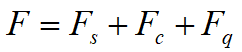
In the equation: F —— test load;
F s — Standard value of the self-weight of steel truss deck;
F c — Standard value of the self-weight of post‑cast concrete and additional reinforcement;
F q — During the construction phase, the standard value of the live load may be taken as 1.5 kN/m. 2.
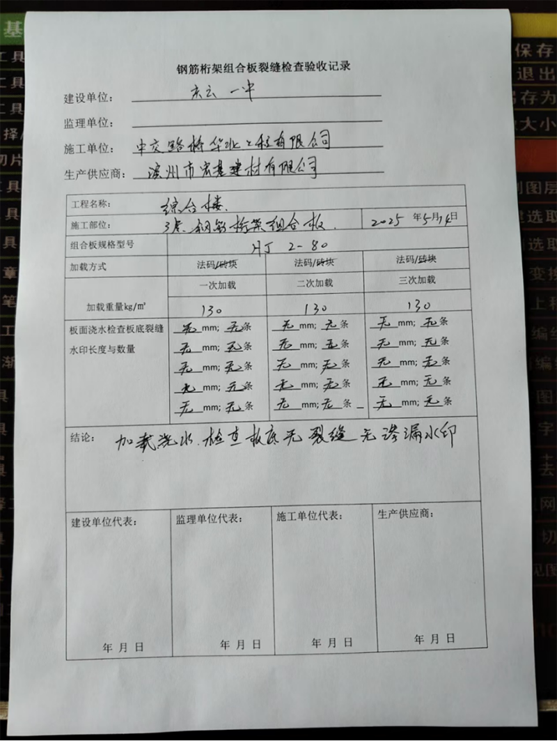
Crack Inspection and Acceptance Record for Steel-Reinforced Truss Composite Slabs
Construction Unit:
Supervising Unit:
Construction Unit:
Production Supplier:
| Project Name: | |||
| Construction Location: | Year Month Day | ||
Composite panel specifications and models |
| ||
Loading method | Weights/Bricks | Weights/Bricks | Weights/Bricks |
Loading weight kg/m² | One-time loading | Secondary loading | Three loads |
|
|
|
|
Watering the slab surface to inspect the length and number of water-stain cracks at the bottom of the slab. | mm; Article | mm; Article | mm; Article |
Conclusion: | |||
Representative of the Construction Unit:
Year Month Day | Representative of the Supervision Unit:
Year Month Day | Representative of the construction unit:
Year Month Day | Production Supplier:
Year Month Day |
1) Truss deck placement support frame
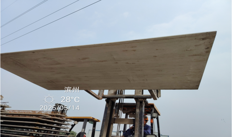
A board is randomly selected from the stockyard.
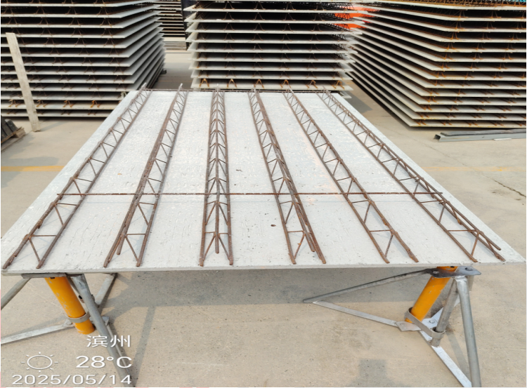
A loading support frame was erected on site.
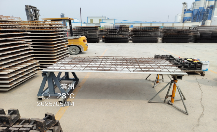
The truss deck is placed on the support frame.
2) After the initial load is applied, pour water onto the top surface of the truss deck; after 10 minutes, inspect the underside of the deck for any signs of water leakage.
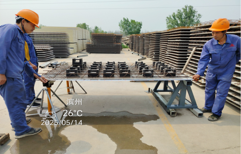
First load of 130 kg/m²
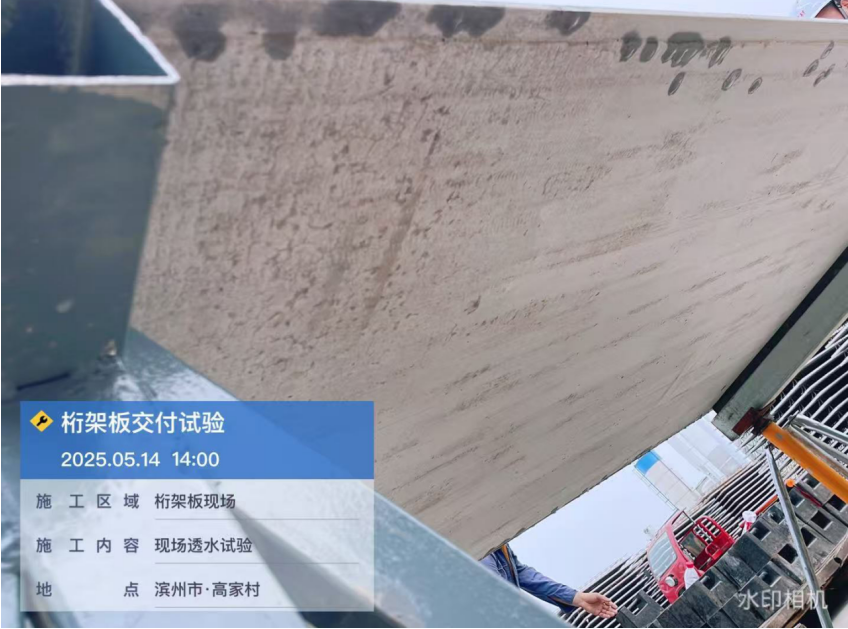
After 10 minutes, observe that there are no water leakage marks on the bottom surface of the panel.
3) After the second load is applied, pour water onto the top surface of the truss deck; after 10 minutes, inspect the underside of the deck for any signs of water leakage.
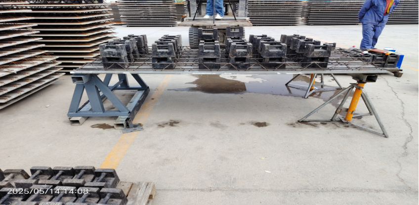
Secondary loading: 130 kg/m²
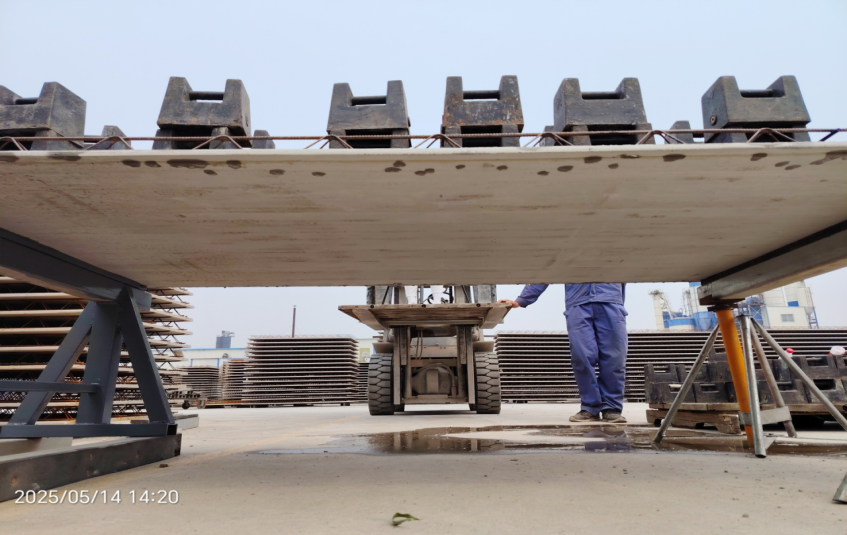
After 10 minutes, observe that there are no water leakage marks on the bottom surface of the panel.
4) After the third loading is completed, pour water onto the top surface of the truss deck; after 10 minutes, inspect the underside of the deck for any signs of water leakage.
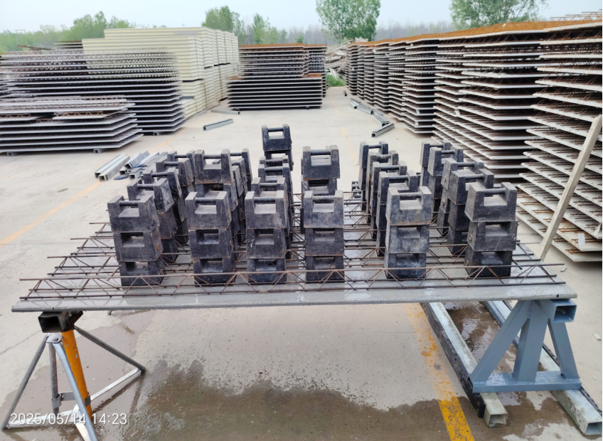
Three load applications of 130 kg/m²
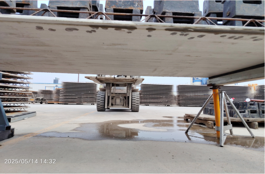
After 10 minutes, observe that there are no water leakage marks on the bottom surface of the panel.
Binzhou Hongji Building Materials Co., Ltd.
June 15, 2025
More information
Truss Deck Crack Detection Plan
2025-07-07


Send us an email, and we’ll have a surprise for you.
Contact Us

HI
Contact us for more special offers!